
A sensitive circuit board can survive a direct drop onto a concrete warehouse floor and still arrive dead on arrival because of an invisible electrostatic discharge. Packaging engineers and procurement teams know that cushioning delicate electronics requires far more than standard packing materials. When uncertified inserts shed loose carbon particles onto assemblies or fail to maintain proper resistance, latent component damage quickly compromises product reliability. Selecting the right conductive foam for ESD protection requires a deliberate balance between verified electrical performance and physical drop cushioning.
You shouldn’t have to compromise on impact dampening to get reliable static shielding, nor should you wait weeks for distant commodity shipments. This guide shows you how to select, specify, and integrate conductive foam packaging to protect sensitive electronics from electrostatic discharge and transit shock. We examine the critical performance differences between closed-cell cross-linked polyethylene and open-cell polyurethane, outline standard ANSI/ESD S541 resistance thresholds, and detail how to integrate precision foam inserts into dependable multi-material packaging systems.
Key Takeaways
- Understand how carbon-impregnated conductive foam for ESD protection provides a permanent ground path to neutralize electrostatic charges before voltage spikes damage sensitive components.
- Compare the operational differences between conductive, static-dissipative, and topical anti-static materials to eliminate risks like humidity dependency, chemical migration, and carbon sloughing.
- Evaluate closed-cell cross-linked polyethylene against open-cell polyurethane to balance pin-insertion retention with multi-axis drop-shock cushioning.
- Discover how custom fabrication methods, such as CNC routing and die cutting, integrate foam inserts into complete protective packaging kits.
- Use a proven technical specification checklist to clarify component dimensions, weights, and resistivity requirements before requesting vendor prototypes.
Fundamentals of Conductive Foam for ESD Protection
Static charges build quietly during everyday assembly and transport. When a handler touches an ungrounded component, thousands of volts can discharge in nanoseconds. High-reliability electronics require packaging that drains charges instantly. Unlike standard packaging that merely insulates or generates friction charges, engineered electrostatic discharge materials create a controlled path to bleed static safely away before electrical potential can arc.
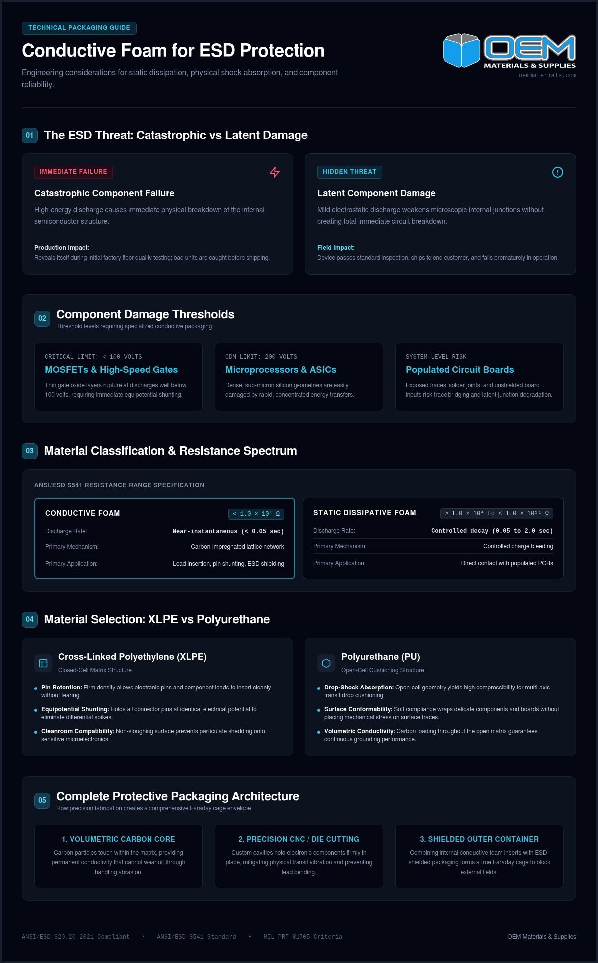
Carbon-impregnated foam incorporates conductive carbon black particles throughout its polymer matrix. These particles touch, forming an interconnected microscopic lattice. When static energy contacts the material, this network drains the charge across the material to ground instead of concentrating voltage spikes on exposed leads. This protection proves vital for components vulnerable to low-voltage thresholds:
- MOSFETs and High-Speed Gates: Thin gate oxide layers can rupture at discharges well under 100 volts.
- Microprocessors and ASICs: Dense, sub-micron silicon geometries are easily damaged by rapid energy transfers.
- Populated Printed Circuit Boards: Traces, solder joints, and unshielded board inputs risk trace bridging or component degradation.
The greatest threat in electronics shipping is latent component damage. Catastrophic failures reveal themselves during initial quality testing on the factory floor, allowing bad units to be caught early. Latent defects are far more insidious. A mild electrostatic discharge can weaken internal junctions without immediate failure. The device passes inspection, ships to the customer, and then fails prematurely during field operations. Implementing certified conductive foam for ESD protection establishes an equipotential envelope that keeps all leads at the same electrical potential, eliminating differential voltage spikes entirely.
How Conductive Foam Mitigates Electrostatic Discharge
When an operator or metallic cart contacts the packaging, charges flow rapidly through the carbon network rather than arcing into protected components. Standard surface coatings only offer surface-level conduction that can wear away under abrasion. Carbon-loaded foam delivers true volumetric volume resistivity, meaning the core conducts just as effectively as the exterior skin. Combining internal conductive inserts with an ESD-shielded outer container creates a complete Faraday cage, attenuating electrostatic fields during transit.
Industry Standards and Surface Resistivity Thresholds
Electronics packaging must align with ANSI/ESD S20.20-2021 standards to safeguard devices susceptible to Human Body Model discharges of 100 volts or Charged Device Model events down to 200 volts. Under ANSI/ESD S541, packaging materials must satisfy strict electrical resistance limits. True conductive foam operates strictly below 1.0 x 10^4 ohms, which ensures near-instantaneous grounding. For military, defense, and aerospace contracts, materials often refer to MIL-PRF-81705 performance criteria, requiring verified static decay rates and durable electrostatic shielding.
Conductive vs Static Dissipative vs Anti-Static Packaging Foam
Specifying the wrong grade of protective foam puts entire shipments at risk. Buyers often see black and pink materials treated as interchangeable static controls, but their electrical physics function in fundamentally different ways. According to established EOS/ESD Association guidelines on static control materials, packaging inserts fall into three primary categories based on surface resistance, charge transfer speeds, and material longevity.
The table below outlines the core operational differences between these common packaging options:
| Material Classification | Surface Resistance Range | Discharge Rate | Primary Packaging Application |
|---|---|---|---|
| Conductive Foam | Strictly < 1.0 x 10^4 Ω | Near-instantaneous (< 0.05 sec) | Lead insertion, equipotential pin shunting, ESD shielding |
| Static Dissipative Foam | ≥ 1.0 x 10^4 to < 1.0 x 10^11 Ω | Controlled decay (0.05 to 2.0 sec) | Direct contact with populated PCBs to avoid CDM sparking |
| Anti-Static Foam (Pink) | ≥ 1.0 x 10^11 Ω (tribocharging) | Slow to none | Non-critical dunnage, hardware, passive structural support |
Surface Resistivity Ranges and Discharge Speeds
Conductive materials operate strictly under 1.0 x 10^4 ohms, routing electrostatic currents immediately to ground. Static dissipative foams fall between 1.0 x 10^4 and 1.0 x 10^11 ohms, though many high-reliability assemblies use a tighter range between 1.0 x 10^6 and 1.0 x 10^9 ohms. This controlled decay prevents rapid sparks that can trigger Charged Device Model failures on live surface-mount devices. Standard pink anti-static foam sits at or above 1.0 x 10^11 ohms, acting primarily as an insulative cushion treated to suppress triboelectric friction charges.
Shelf Life, Humidity Dependence, and Chemical Contamination Risks
Pink anti-static foam relies on topical chemical surfactants, typically hygroscopic fatty amines, to draw ambient moisture from the air. In dry warehouse conditions below 20 percent relative humidity, these materials lose their antistatic properties completely. The surfactants also migrate over a typical shelf life of 6 to 12 months, leaving an oily residue that tarnishes gold, silver, or soldered leads.
Carbon-loaded conductive foam for ESD protection eliminates these contamination risks. The conductive carbon particles remain permanently embedded within the polymer resin, operating reliably across 0 to 100 percent relative humidity without off-gassing. For engineering teams evaluating materials for mission-critical subassemblies, you can request a quote for custom ESD packaging tailored to your component tolerances.
Selecting Foam Materials: Cross-Linked Polyethylene vs Polyurethane
Balancing mechanical cushioning against electrical conductivity is a core challenge in electronics packaging. If you select a foam solely for its static drainage, your components may bottom out during transit impacts. Conversely, choosing purely for soft cushioning can leave leads vulnerable to bending or charge accumulation. Selecting engineered foam packaging solutions requires matching component mass, lead fragility, and shipment cycles to the correct polymer matrix.
Closed-Cell Conductive Polyethylene for Pin Insertion and Rigidity
High-density cross-linked polyethylene (XLPE) features a rigid, closed-cell structure. It is the industry standard for dual-in-line packages, integrated circuit chips, and pin-grid arrays. Component leads press directly into the dense matrix without bending, which keeps all pins at equal potential. This design reflects proven NASA reliability practices for ESD control, ensuring electrical safety across critical flight and defense hardware.
Unlike standard cellular foams that may use chemical blowing agents with corrosive sulfur or chloride byproducts, cleanroom-grade conductive XLPE is non-corrosive. It won’t tarnish silver or gold-plated contacts during long storage cycles. The material also maintains dimensional stability under heavy loads, eliminating the risk of components sinking to the container floor.
Open-Cell Conductive Polyurethane for Shock Absorption and Cushioning
Open-cell conductive polyurethane (PU) delivers progressive deceleration under impact. It excels at protecting calibrated assemblies, power supplies, optical sensors, and sensitive populated circuit boards from multi-axis drop shocks. The interconnected cell walls flex to dampen continuous transit vibrations.
Engineers must consider abrasion risks when using PU foams. Repeated sliding contact against sharp board edges or micro-vibrations can shear open cell walls, shedding microscopic particles into delicate subassemblies. For an in-depth look at dynamic cushioning curves and cell mechanics, consult the industrial guide to foam inserts engineering and material selection.
Density and Load Bearing Capacities for Sensitive Electronics
Conductive foam performance relies on precise density selection:
- High-Density XLPE (2.8 to 3.1 PCF): Provides the firm structural resistance needed for IC pin insertion and rigid shunting bases.
- Medium-Density XLPE (1.8 to 2.2 PCF): Delivers edge protection and blocking for heavy electronic chassis.
- Cushioning PU (1.2 to 2.2 PCF): Provides low-deflection dampening for fragile subassemblies.
Calculating the static stress window (component weight divided by the bearing contact area in pounds per square inch) ensures the foam functions in its optimum deceleration curve. Proper load balancing prevents long-term foam creep, ensuring conductive foam for ESD protection retains both its physical cushioning and static pathways across the entire supply chain.
Custom Fabrication and Packaging Integration for OEMs
Off-the-shelf foam sheets rarely satisfy the physical or electrical demands of production lines. Loose circuit boards shifting inside an oversized container generate friction, risk lead bending, and slow down packing workers. Experienced packaging engineers use custom packaging design services to engineer precision cavities that hold delicate subassemblies securely in place. Integrating conductive foam for ESD protection directly into complete kitting assemblies eliminates in-transit movement and speeds up assembly workflows.
Precision Die-Cutting and CNC Routing for Component Trays
High-volume manufacturing programs benefit from steel-rule die cutting, which stamps out thousands of identical foam inserts with tight dimensional tolerances. For lower volumes, large footprints, or rapid prototyping cycles, CNC waterjet cutting and multi-axis routing shape pockets without upfront tooling costs. These custom cavities incorporate dedicated channels for wire harnesses and integrated finger lift cutouts. Floor personnel can seat or remove fragile parts without gripping sensitive board edges.
Combining ESD Foam Inserts with Corrugated Shipping Containers
A conductive insert provides an equipotential ground plane, but full transit protection requires Faraday-cage shielding outside an Electrostatic Protected Area. Fabricators achieve this by pairing custom foam inserts with custom corrugated boxes treated with static-dissipative or carbon-loaded liners. Multi-material packs unify the outer shipper, conductive cushion, and internal dividers into a single kit. This streamlines procurement and reduces workstation touch points.
Cleanroom Compatibility and Non-Sloughing Requirements
Particulate contamination is just as destructive as electrostatic discharge in medical, optical, and aerospace manufacturing. Commodity open-cell foams can shed microscopic carbon dust under repetitive transit vibration:
- Carbon Sloughing: Loose conductive dust settling between micro-pitch pins can bridge traces, causing electrical shorts on live boards.
- Closed-Cell XLPE Performance: Nitrogen-blown cross-linked polyethylene features fused cell walls that resist abrasion and prevent dusting.
- Outgassing and Chemical Purity: Critical assemblies require formulations free of amides, chlorides, and volatile plasticizers that condense onto optical sensors.
Manufacturing facilities across Southern California can partner with local packaging specialists to verify material purity before production runs. If you need cleanroom-safe inserts fabricated to tight tolerances, request a quote for custom-engineered foam packaging to review your assembly prints and drop-test requirements.
Technical Specification Checklist for Procurement Teams
Procurement teams often encounter costly production delays when transitioning an electronic assembly into volume packaging. Generic requests that simply ask for “black ESD foam” lead to excessive back-and-forth communication, mismatched dimensional tolerances, and delayed first-article approvals. Documenting exact mechanical and electrical parameters upfront accelerates tooling lead times and guarantees that your conductive foam for ESD protection performs reliably throughout transit.
Key Data Points to Define Before Requesting Quotes
To eliminate quoting delays and support rapid prototyping, engineering and purchasing teams should compile four essential technical details:
- Component Geometry and Mass: Provide detailed CAD models or physical dimensions, part weight, and center-of-gravity profiles to calculate exact foam deceleration and cavity clearances.
- Electrical Thresholds: Clarify whether the application requires conductive shunting below 1.0 x 10^4 ohms per ANSI/ESD S541 or static-dissipative dissipation to mitigate Charged Device Model risks.
- Cleanliness and Metallurgy: Define any cleanroom cleanliness standards, outgassing restrictions, or sensitivity to particulates to prevent carbon sloughing on gold- or silver-plated contacts.
- Production Volumes: State projected annual usage and recurring batch sizes, which dictate whether waterjet cutting or steel-rule die tooling offers the most practical manufacturing route. Total packaging costs depend heavily on material volume, foam density, and cavity complexity.
Sourcing ESD Packaging Solutions Across Southern California
Relying on distant commodity distributors introduces lengthy shipping lead times when designs require rapid adjustments. For electronics, aerospace, and medical device manufacturers across Orange County, Los Angeles County, the Inland Empire, and San Diego County, working with a regional packaging fabricator provides direct engineering collaboration. Local design teams can turn around physical prototypes quickly, allowing quality managers to perform fit checks and drop testing without stalling assembly schedules.
Regional partnerships also simplify production inventory management. By establishing vendor-managed inventory agreements, facilities maintain buffer stocks of critical foam sets and corrugated shippers close to assembly lines. Backed by reliable just-in-time delivery, local plants can stage packaging supplies in lockstep with fluctuating production schedules, eliminating stockouts and freeing up valuable warehouse floor space.
Upgrade Your Component Packaging with Engineered ESD Protection
Safeguarding sensitive electronics against transit damage requires balancing verified electrical conductivity with precise mechanical dampening. Specifying permanently carbon-loaded conductive foam for ESD protection eliminates latent component defects, prevents humidity-related performance drops, and stops particle sloughing across your supply chain.
OEM Materials & Supplies delivers engineered packaging solutions tailored to high-reliability manufacturing. Through precision CNC routing, waterjet cutting, and steel-rule die fabrication, we build unified packaging kits that integrate custom ESD foam inserts with industrial corrugated boxes. Our regional facilities provide reliable just-in-time delivery and vendor-managed inventory programs across Orange County, Los Angeles County, San Diego County, and Riverside.
Ready to protect your assemblies and streamline your packaging workflow? Request a custom ESD foam quote and prototype today. Provide your component dimensions, board weights, drop-test requirements, and annual usage to receive a tailored recommendation engineered for your production schedule.
Frequently Asked Questions
What is the difference between conductive foam and pink anti-static foam?
Conductive foam contains permanent carbon black networks that yield a surface resistance under 1.0 x 10^4 ohms, draining charges almost instantly. Pink anti-static foam relies on topical chemical surfactants that merely reduce friction charging. These chemical coatings require ambient humidity to function, degrade within 6 to 12 months, and can transfer oily residues onto sensitive circuitry.
How do I know if my electronic components require conductive foam?
Your assemblies require conductive foam if they contain components vulnerable to electrostatic discharges below 100 volts, such as bare microprocessors, MOSFETs, and high-density ICs. Devices with exposed pins benefit specifically from conductive cross-linked polyethylene, which shunts leads together at equipotential. If an assembly carries high Charged Device Model risks, static-dissipative foam provides a gentler bleed-off path.
Does conductive foam lose its ESD protective properties over time?
No, high-grade conductive foam for ESD protection does not degrade electrically over time. Because conductive carbon black particles are permanently dispersed throughout the base polymer resin, the electrical pathways remain active indefinitely. Unlike topical chemical treatments, carbon-impregnated foams maintain consistent volume and surface resistivity regardless of age, temperature shifts, or dry warehouse conditions.
Can conductive foam cause short circuits if battery-powered boards are shipped active?
Yes, placing an active, battery-powered circuit board directly onto conductive foam will cause electrical shorting. Because conductive foam has resistance below 1.0 x 10^4 ohms, it acts as a low-resistance path across exposed solder joints and battery terminals. For live or battery-backed units, engineers specify static-dissipative materials or design custom routed trays with relief pockets around live battery leads.
What causes carbon sloughing in conductive foam and how can it be prevented?
Carbon sloughing occurs when mechanical abrasion shears open-cell polyurethane walls, shedding microscopic carbon particles onto circuit assemblies. These loose particles can settle between fine-pitch component leads and trigger electrical shorts. To prevent particulate contamination, specify closed-cell cross-linked polyethylene foam. Nitrogen-blown XLPE features fused cell structures that resist dusting and meet strict cleanroom standards.
Is closed-cell or open-cell conductive foam better for shipping populated circuit boards?
Closed-cell cross-linked polyethylene works best as a rigid base to support board perimeters or shunt through-hole pins without shedding particles. Open-cell conductive polyurethane excels at absorbing multi-axis drop shocks and continuous vibration around delicate components. Many high-reliability packaging kits integrate both materials, using high-density closed-cell foam for structural pockets and soft open-cell foam for top cushioning.
What industry standards govern the use of conductive foam in electronics packaging?
ANSI/ESD S20.20-2021 sets the baseline operational standard for electrostatic discharge control programs, while ANSI/ESD S541 defines packaging material resistance classifications. Resistance testing follows ANSI/ESD STM11.11 for surface measurements and STM11.12 for volume resistivity. Defense and aerospace packaging contracts also reference military specifications like MIL-PRF-26514 for cushioning polyurethane foams and commercial descriptions A-A-59135 and A-A-59136 for cross-linked polyethylene.